Four gentlemen helped revolutionize the way we understand electricity and the measures that we can use to calculate the value of electrons flowing through circuits. They were a Frenchman Andre M. Ampere (amps), an Italian called Alessandro Volta (Volts), a German called Georg Simon Ohm (The Ohm), and an Englishman named James Watt (Watt).
[ez-toc]
Simple electrical schematics are easy to read; you only need to remember that the diagram is essentially a map of the circuits. It shows how electricity is introduced into the home, the position of the circuit breakers, and shows which electrical circuits are connected to the individual circuit breakers.
When you first study your home electrical schematics, it can seem like a complicated street map. Keep in mind that electricity always moves from negative to positive. On the way, there will be switches, lights, wall outlets, and electrical consumers, are included, and you begin to understand that it is a very logical way to set out the system.
The Way To Read Electrical Schematics
Electrical schematics are a map of the electrical systems we are studying. They show the route that the electrical current takes, the switches, appliances, or other electrical consumers attached to the circuit, and help understand how the electrical circuit works and diagnose any problems.
Before reading a road map, you need to understand what each symbol means. For example, you need to know which roads are highways, the distances, where towns are, etc.
In the same way, you must understand what the symbols on the electrical schematic diagram mean. It will provide the information you require to understand the direction of the current flows, the amount of current each appliance uses, any switches used to break the circuit, etc.
Just like a physical map is understood better if you know the rule of the road, the more you understand electricity, the easier it is to decipher electrical schematics.
There are four ways electricity is measured these are.
Voltage Is The Potential Energy Of A Circuit
Electricity moves from the negative side of the circuit to the positive.
The measure of voltage is the difference between the voltage available at the negative terminal compared to the positive terminal. Another way of explaining it is that it measures the pressure that is available to send the electrons through the circuit.
Compared to a water system, the voltage would be the pressure differential between the start and the end of the system.
The letters showing voltage in electrical schematics are.
- VAC for alternating current (e.g., 120VAC).
- VDC for Direct current (e.g., 12VDC).
Amps Are The Speed Of The Electrons
The measure of amps is the same as a traffic policeman checking people for speeding. The official achieves this with a radar monitoring device that calculates oncoming cars’ speeds.
In the same way, an ammeter measures the number of electrons that pass a fixed point in an electrical circuit in one second.
6.28 x 10¹⁸ electrons passing one point of a circuit in one second equals one amp.
On an electrical schematic diagram, amps are shown as a number with an A next to it. For example, 15A.
Watts Are The Measure Of The Amount Of Work The Electrons Do
Watts is the measure of power in an electrical circuit.
Another definition is the rate at which energy is transferred or at which electrical work is performed.
Multiplying the voltage by the amps results in the watts.
In an electrical schematic diagram, watts are shown as a number (the value) with the word Watts (or the letter W).
Ohms Is The Measure Of Resistance
Ohms is the measure of the resistance in a circuit between two points.
Put another way, the measurement of Ohms is the electrical resistance of a material or an electrical device.
Ohms are calculated by dividing the voltage over the Amps value.
On an electrical schematic diagram, Ohms is represented by the Greek letter omega “Ω.”
Now that we can measure the electrical current, let’s add some symbols to understand how it fits into an electrical schematic diagram.
The Commonly Used Symbols Are
The following are the symbols that make up simple electrical Schematics.
The Circuit
The conductive material (wire or the circuits in a circuit board) is always shown as a solid line.

Switches
The diagram for on-off switches in an electrical schematic is.

This diagram shows a simple on/off single throw switch. There are many different switches, all illustrated by other symbols, depending on the type of switches in the schematic diagram.
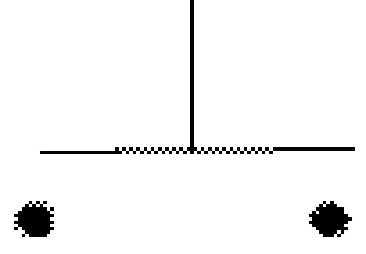
The following push button, which is a “normally open” switch, is an example of the differences in the way different electrical switches are visualized.
Resistance Is Measured In Ohms
Current consumers such as air conditioners, hot plates, heaters are shown as resistors, measured in Ohms.
Schematic diagrams show resistors with the following symbol.

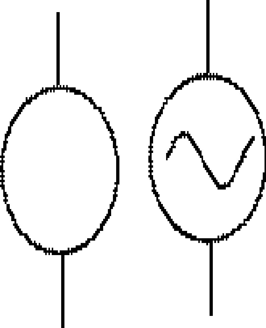
Power Source
The power source is shown differently depending on whether the current is alternating (AC) or Direct (DC).
The symbol on the left shows a Direct Current (DC) power source, and the one on the right shows an Alternating Current (AC) power source.
The symbols of some other components which make up an electrical schematic diagram are as follows.
A Light Bulb
A light bulb will be shown on an electrical schematic as a cross inside a circle.

A Wall Socket
A wall socket is shown with the following graphic.

What Would A Total Home Electrical Schematic Look Like?
The wiring in a home will show all the house rooms connected to the various parts of the circuit.
- The circuit will start at the primary utility supply source (120V or 240V alternating current).
- The positive and negative wires will be drawn as two lines to the circuit breaker box.
- The main circuit breaker will show the positive and negative current supplies to the individual circuits, starting at the circuit breakers.
- The individual circuits will then be shown separately as lines drawn from the individual circuit breakers to the rooms or series of rooms.
- The circuit for each room will include one or more switches and wall outlets.
- Any electrical consumer other than lights will be shown as a resistance symbol.
General
As discussed previously, a house electrical schematic diagram serves three purposes.
- It enables the electrical system, wiring gauge, and circuit breakers to be correctly sized.
- It helps the house owners understand the number of circuits, switches, and plugs in each room.
- If the system is faulty, an electrical schematic enables the electrician to understand how the circuit was constructed and identify possible current anomalies against the wiring.
Conclusion
An electrical schematic diagram of a home is just a map showing how the circuits are laid out.
By understanding the layout and the size of the current, which will be drawn by appliances, stoves, air conditioners, and other consumers, the electrician can calculate the gauge of wire to be used and the size of the circuit breakers.
References
https://www.physicsclassroom.com/class/circuits/Lesson-4/Circuit-Symbols-and-Circuit-Diagrams
http://apps.usd.edu/coglab/psyc770/resistors/ohms4beginner.html
How to Read Electrical Schematics
http://www.rses.org/assets/serviceapplicationmanual/630-141.pdf